Feb 26 2013
New assembly methods at Toyota
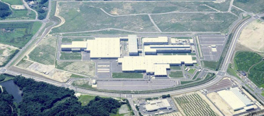
Toyota’s latest plants in Ohira, in Japan’s Miyagi prefecture and in Tupelo, Mississippi, feature new approaches to assembly. According to press reports, the Miyagi plant is small, with 900 employees making 250 cars/day for export to the US, with a plan to double output and employment. It was designed to require a minimal investment and be easy to change. The plant started operations shortly before the Fukushima earthquake and, even though it is the Northern part of Japan that was most affected, it resisted well and was able to resume operations about six weeks later.
This is how Barry Render described it:
“The Miyagi factory is designed for advanced low-volume, hyperefficient production, with 1/2 the workers and 1/2 the square footage of Toyota’s 16 other plants. Inside, half-built Corollas and Yaris sit side-by-side, rather than bumper-to-bumper, shrinking the assembly line by 35% and requiring fewer steps by workers. Instead of car chassis dangling from overhead conveyor belts, they are perched on raised platforms. This is 50% cheaper, and also reduces cooling costs by 40% because of lower ceilings. Finally, the assembly line uses quiet friction rollers to move the cars along. The rollers use fewer moving parts than typical chain-pulled conveyor belts.”
Toyota is not providing details, but I have been able to glean some information about it from the press and Barry Render’s blog, on the following features:
- Side-by-side assembly
- Modular paint booths
- Friction roller conveyors
- Elevated platform versus suspension conveyor
This is followed by a few conclusions.
Side-by-side assembly

I have seen side-by-side assembly at the Volvo Bus factory in Turku, Finland. In the picture of the building below, bus bodies are assembled in the hall on the left, side-by-side under they are mounted on a chassis and move forward on their wheels, laid out front to back in the hall you see in the background.


The ratio of width to length is more favorable to this arrangement for buses than for cars. A straight assembly line with a front-to-back arrangement throughout would require a long and narrow building and a snaking line would have problematic turnarounds. With cars, the side-by-side arrangement seems suitable for work done at the front or the back of the car, such as installing headlights or bumpers. but less for work that requires access from the middle, such as installing instrument panels or upholstery. The following press picture (AP), however, shows an assembly operation done inside the car body in what appears to be a side-by-side layout. It implies that space for the part cart must be provided between cars, which forces them apart.

None of the available pictures from the Miyagi plant shows the raku-raku seat that was a prominent feature of the early 1990s designs and made it easier for operators to work inside the car bodies. Not only is a raku-raku seat an added investment, but it is also easier to use in a front-to-back than in a side-by-side layout.

Modular paint booths
I could not find pictures or sketches of the Miyagi painting system. Following is how CNN Money described it on 2/18/2011:
“…Toyota developed a modular paint spray line. The modules can be built somewhere else and are assembled at the plant in a much shorter time. Advantage: Cost savings. However, you don’t build a modular paint spray line factory somewhere unless you intend to build a lot of paint spray lines. Usually, cars get three coats of paint, usually water-based, and usually each coat is dried with heat. Not in Ohira. Here, the third coat is applied onto the still wet second coat and both are dried together. Advantage: Huge energy savings, faster paint time. Lower expenses…”
Friction roller conveyors
Following is how CNN Money described the Miyagi conveyor systems on 2/18/2011:
“Where the car moves along the floor, factories usually have below ground pits that house the motors, chains and gears that keep the line moving. Not in Ohira. Here, the cars move on maybe a foot high conveyor system that is simply bolted into the concrete flooring. Advantage: Cheaper to build, cheaper to tear down and rebuild somewhere else. The line can be lengthened or shortened at will. The assembly line doesn’t ‘grow roots’ as they say in Toyota-speak.”
Note that the sketch shows car bodies without wheels. In this system, the bar supporting the cars forms
A photographs of final assembly at Ohira shows operations done further downstream, with the wheels on:

In this picture, the floor the operators stand on is flush with the assembly line, meaning that it is either a classical line with the drive mechanism in a pit under the floor, or the operators are in a raised platform spanning the length of this assembly line segment.
Elevated platform versus suspension conveyor

The following photographs contrast the suspension conveyor approach as previously used at Toyota with the elevated platform at Tupelo, Mississippi:
From these pictures, it is clear that the elevated platform is a cheaper system to build, but I can see two issues with it:
- Flexibility in vehicle widths. The Yaris and the Corolla differ in width by less than half an inch, and therefore the same elevated platform can accommodate both. A Land Cruiser, on the other hand, is 11 inches wider, which makes you wonder whether it could share an elevated platform with the Yaris. The jaws of the suspension conveyor, on the other hand, look adjustable to a broad range of widths.
- Ergonomics. Working standing with your head cocked back and your arms overhead is just as ergonomically inadequate in both cases. By contrast, the VW plant in Dresden, Germany, uses suspended conveyors that can tilt the body, which is both ergonomically better and much more expensive:

Conclusions
The journalists take on the Ohira plant is that it is intended to prove a design for low-volume, low-cost, high-labor content plants that can be deployed easily in emerging economies with small markets. The designs of the early 1990s instead used more automation to make the work easier for an aging work force, with tools like the raku-raku seat. This is a different direction, addressing different needs. But why build it in Northern Japan rather than, say, the Philippines? It shows Toyota’s commitment to domestic manufacturing in Japan, and it is easier to test and refine the concept locally than overseas.


Mar 3 2013
From Ybry charts to work-combination charts
This is a screen shot from yesterday’s evening news on the France 2 channel, part of a story about TGV high-speed trains used on regular tracks to bring vacationers to ski areas. The TGVs, of course run at regular speeds on these single line tracks and must stop at sidings to let regular trains through in the opposite direction. In an earlier post, I discussed the charts invented by Charles Ybry in 1846 for railroad scheduling, and this newscast shows that they are still used in railroads today. Besides railroad scheduling, they are also used in the management of multiple, concurrent projects, and I believe they were the basis for Toyota’s work combination charts.
The x-axis is time; the y-axis, position along the line. On the chart, the downward lines represent trains going down the line; the upward lines, trains coming up the line. When and where the lines cross, trains cross, and there must be a siding available. The news story had the TGV pilot call in his position on a siding to a control center in Chambéry where the chart was displayed. On the high-speed TGV lines, the signalling is all electronic, and the system automatically knows where the trains are; when you run a TGV train at reduced speed on a regular line, however, it seems that the driver has to report what happens the old-fashioned way.
I learned about these charts in Edward Tufte’s Envisioning Information, where he describes them as a special case of a “narrative of space and time.” Among the examples he gave were a similar railroad scheduling application from Switzerland 80 years ago and the development of Wagner’s operas over almost 50 years in the 19th century:
Work combination charts are a tool to design and communicate about production jobs that require operators to perform a sequence of operations on multiple machines that operate automatically between visits. This is a Japanese example of such a chart:
The concept looks similar, doesn’t it? I found this chart particularly useful when you need to plan the activities of more than one operator, as in the following example:
In the Legend, “Manual In” refers to time spent by the operator on the machine with it stopped; “Manual Out,” time spent on the machine while it runs.
To this date, in the US, this powerful technique is far from enjoying the popularity it deserves. It is generally perceived as “too complicated” and I still don’t know of any software tools that fully support it. In designing jobs that involve interactions between human and machines, however, the consequence of not using it is leaving about 50% of the potential productivity improvement on the table. It may take a project team an extra day to do it, but the result is achieving a 40% productivity increase instead of 20%. Details are discussed in Chapter 7 of Working with Machines.
Share this:
Like this:
By Michel Baudin • Technology 3 • Tags: industrial engineering, Manufacturing engineering, Operator job design, Railroad, Scheduling, TGV, Toyota, Work-combination charts